Hitsauksen ABC
Understanding and preventing common welding defects
15. helmikuuta 2024
Hitsaus vaatii tarkkuutta, mutta jopa ammattitaitoiset hitsaajat voivat kohdata virheitä. Yleisten hitsausongelmien ymmärtäminen on ratkaisevan tärkeää laadukkaan lopputuloksen varmistamiseksi. Seuraavassa on joitakin usein esiintyviä hitsausvirheitä ja miten niitä voidaan välttää.
Susanna Norja
Lack of fusion
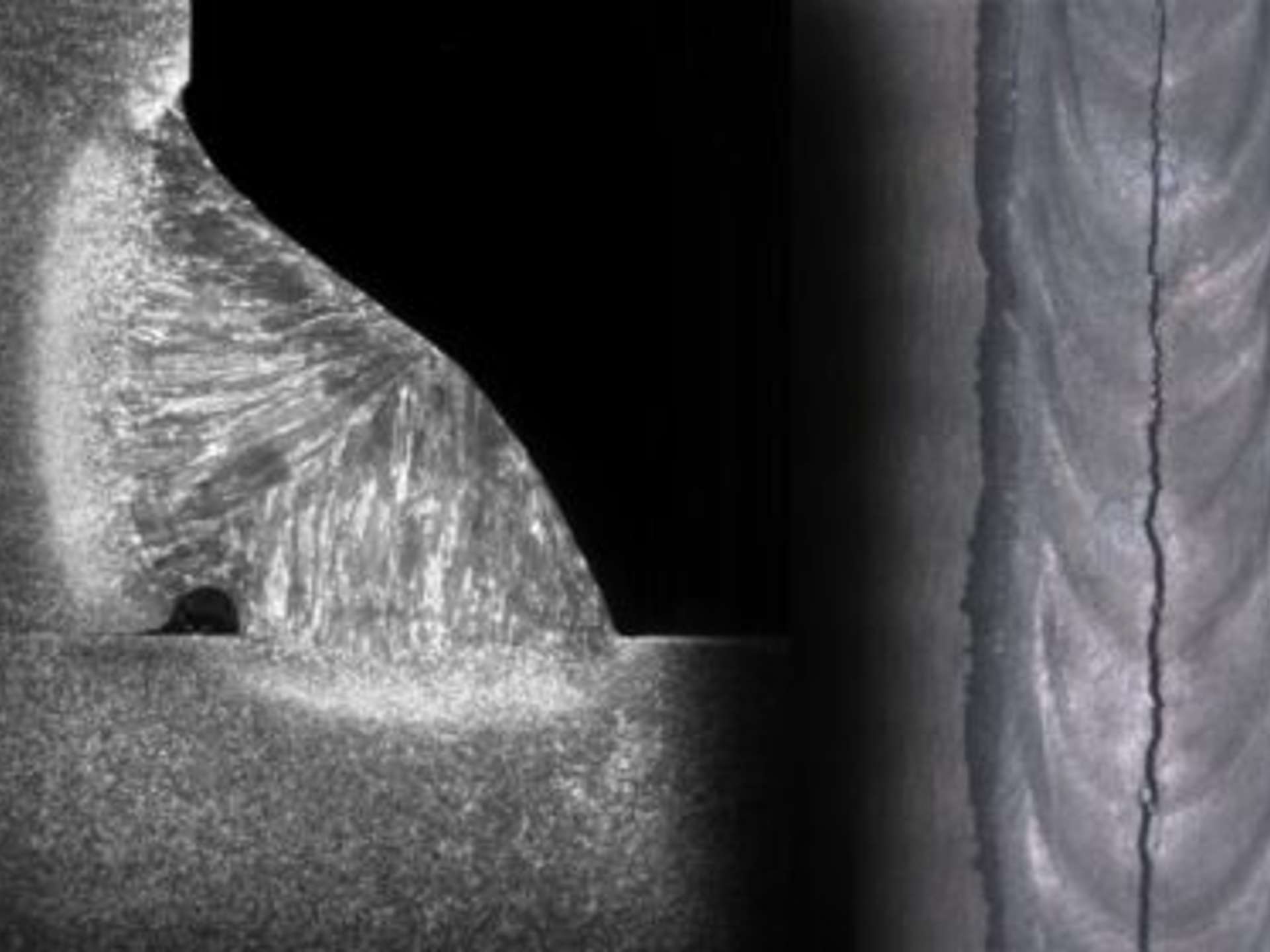
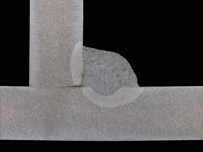
When two pieces of metal are welded together, they should melt and bond at the interface to create a strong joint. If the weld metal doesn't fully fuse with either the base metal or the previous weld layer, it can result in weak and unreliable joints. This is known as lack of fusion, and it occurs when there is insufficient melting and bonding. To avoid this problem, it's essential to properly prepare the joint and use the correct welding technique and parameters.
POSSIBLE CAUSES | HOW TO AVOID? |
|---|---|
Too narrow joint preparation | Ensure that the joint preparation is sufficiently wide |
Incorrect torch/electrode angle | Make sure the torch/electrode angle will produce adequate side-wall fusion |
Excessively high current or too low a welding speed, which creates a weld pool flooding ahead of the arc, resulting in insufficient penetration | Select welding parameters (high welding current, short arc length, and not too high a welding speed) that promote sufficient penetration without causing flooding |
Impurities on the joint faces | Clean the joint faces |
’Downhill welding’ | Use vertical up welding |
Too long arc/too high voltage | Use shorter arc/less voltage |
Too low heat input | Increase heat input |
Porosity
Welding porosity refers to forming small air pockets or pores that weaken the weld. These pores occur when undesired gases get trapped within the molten weld puddle. To avoid porosity, it is crucial to maintain good gas shielding, ensure proper cleaning of the joint faces, and use correct welding parameters.
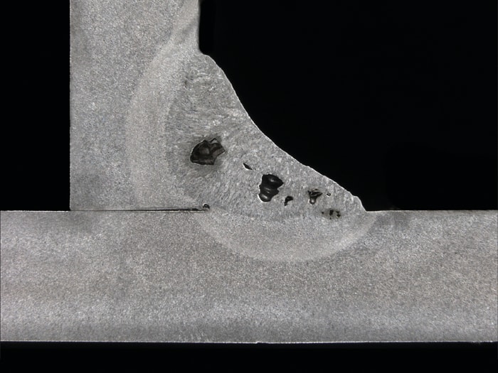
POSSIBLE CAUSES POSSIBLE CAUSES | HOW TO AVOID? |
|---|---|
Poor gas shielding | Seal any air leaks, reduce any excessively high gas flow rates, avoid weld pool turbulence and drafts |
A wet electrode | Dry the electrode |
Impurities on the joint faces, such as rust, primer | Clean the joint faces |
Too long arc/high voltage | Decrease voltage |
Too low heat input | Use higher heat input |
Lack of penetration
Lack of penetration in welding is a term used to describe a defect where the weld metal does not fully extend the joint thickness. This defect can weaken the joint and increase the risk of potential failure. To avoid this, it is important to adjust welding parameters and techniques to ensure complete weld penetration into the base metal.
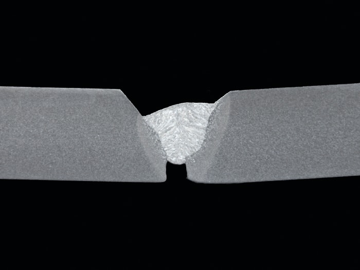
POSSIBLE CAUSES | HOW TO AVOID? |
|---|---|
Poor joint design or preparation | Expand the root opening or decrease the size of the root face |
Excessively long arc length | Weld with a shorter arc / reduce the voltage |
Too large an electrode diameter | Use a smaller electrode |
Excessively high welding speed | Decrease the welding speed |
Too small heat input | Increase heat input |
Undercutting
Undercutting in welding is a defect that happens when a groove or depression runs along the toe of the weld. This occurs when the filler metal fails to properly fill the melted base material. As a result, the base of the weld joint has a concave shape. Unfortunately, this flaw reduces the welded joint's structural integrity, making it more prone to cracks and failures.
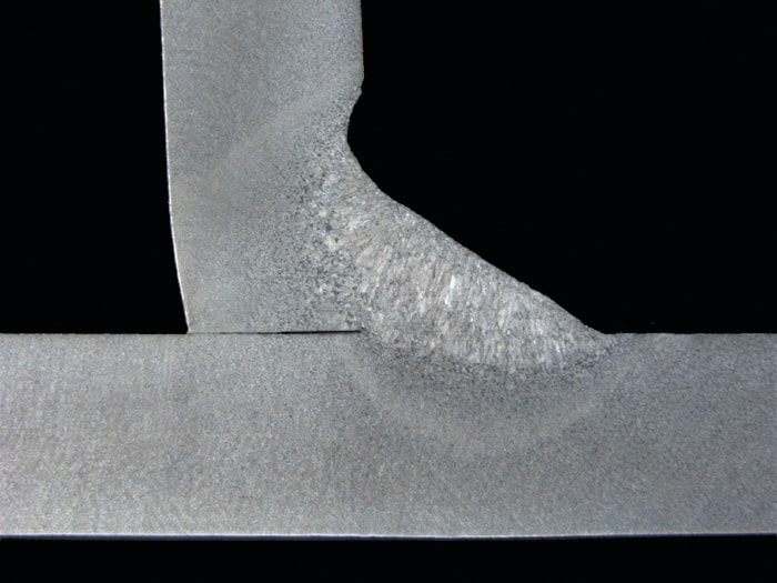
POSSIBLE CAUSES | HOW TO AVOID? |
|---|---|
Too long arc/voltage | Reduce the voltage |
Incorrect angle of the electrode | Use appropriate electrode angles |
Excessive weaving of the electrode | Perform the weaving motion properly, by pausing at each side of the weld bead |
Excessively high current | Reduce the current |
Too large throat thickness | Use multipass welding |
Crater cracks and crater pipes
Crater cracks occur when the weld pool cools down too quickly. These cracks make the weld weaker and more prone to failure. They usually spread outwards from the end of the weld crater. Crater pipes, on the other hand, are defects that appear at the end of a weld when the welding arc stops. They can be shallow depressions or elongated pores. Crater pipes form due to techniques like suddenly stopping the wire feed or using autogenous methods (such as TIG welding). Proper welding techniques and parameters, along with adding filler material at the end of the weld, can help prevent these types of cracks.

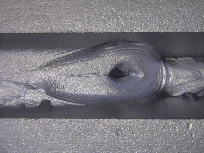
POSSIBLE CAUSES | HOW TO AVOID? |
|---|---|
Incorrect stopping technique | Stop welding by moving the arc backward a little or to the groove side |
Rapid solidification of a large weld pool when the welding current is switched off | Progressively reduce the welding current, to decrease the weld pool size |
Slag inclusions
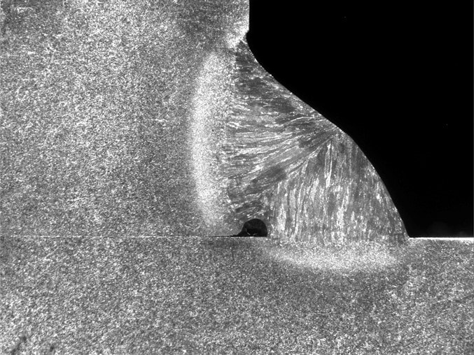
Slag inclusions are a frequent type of welding defect that arises when slag, a by-product of welding, gets stuck inside the weldment. This can cause a range of performance problems in the long run. To avoid this problem, cleaning thoroughly and using the appropriate welding technique is crucial.
POSSIBLE CAUSES | HOW TO AVOID? |
|---|---|
Voids caused by inadequate overlap of two adjacent weld beads | Use the correct electrode size and angle, and use welding techniques that produce smooth weld beads |
Insufficient slag removal | Remove all slag between runs |
Too low heat input | Increase the heat input |
Slag flooding ahead of the arc | Aim the arc toward the weld pool |
Too narrow joint | Increase the joint angle |
Excessive penetration
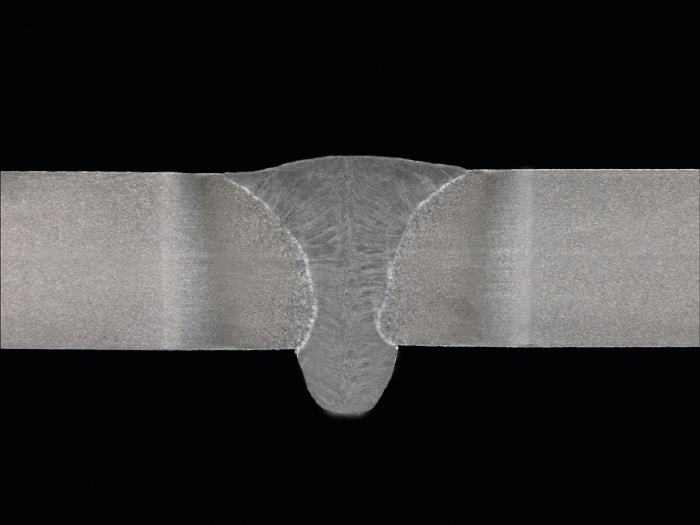
Excessive penetration in welding refers to a situation when weld metal penetrates deeper into the base metal than intended. To manage the level of penetration, controlling the heat input and speed of welding is crucial. This phenomenon is particularly important in pipe welding, as it can impact fluid flow and cause erosion and corrosion issues.
POSSIBLE CAUSES | HOW TO AVOID? |
|---|---|
Too high heat input to the joint | Reduce the heat input |
Too large air gap | Use a smaller air gap |
Too small a root face | Enlarge the root face |
Spatter
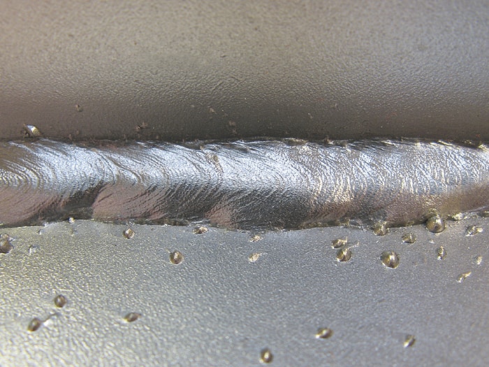
During the welding process, small droplets of molten metal can scatter from the weld pool and stick to various surfaces. This is called spatter, and it can negatively affect both the appearance and quality of the weld. The primary cause of spatter is an unstable welding arc. To reduce spatter, it's important to fine-tune the welding parameters and potentially adjust the gas flow or mixture. By effectively managing spatter, you can ensure that your welds are of high quality and visually appealing.
POSSIBLE CAUSES | HOW TO AVOID? |
|---|---|
Inappropriate welding parameters | Adjust the welding parameters |
Too long an arc / excessively high voltage | Weld with a shorter arc / reduce the voltage |
Wet, uncleaned, or damaged electrodes | Use dry and undamaged electrodes |
Impurities on the fusion faces or in the filler materials – e.g., rust | Grind the fusion faces, and use clean filler materials |
Magnetic arc blow | Change the position of the earth return clamp / weld toward the clamp / bend the stick/torch in the direction of the blow |
Incorrect polarity | Change the polarity |
Linear misalignments (Mismatch)
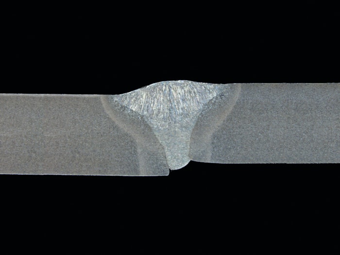
Linear misalignment in welding is a defect that occurs when the edges of the weld joint are not aligned correctly in a straight line. This results in a deviation or offset along the length of the weld bead. To minimize this defect, it is important to use proper fixturing and alignment techniques and adhere to welding procedures.
POSSIBLE CAUSES | HOW TO AVOID? |
|---|---|
Poor component fit-up before welding | Perform the joint fit-up work accurately |
Deformations during welding | Rigidly fix parts to be welded in place, and use the correct welding sequence |
Breaking of tacks during welding | Perform the tack welding properly |
Uncorrect tolerance of the welding components | Check tolerances |
Excessive fillet weld asymmetry
Excessive fillet weld asymmetry in welding occurs when the two legs of a fillet weld are not of equal length, leading to an uneven distribution of weld material. This imbalance can affect the structural integrity and strength of the welded joint. This asymmetry can compromise the weld's ability to withstand loads and stresses as intended, potentially leading to premature failure or deformation under operational conditions.
Furthermore, excessive fillet weld asymmetry refers to a condition where the fillet weld's shape deviates significantly from the desired idealized design. Fillet welds are commonly used to join two components at an angle of 90 degrees and are characterized by their triangular cross-section.
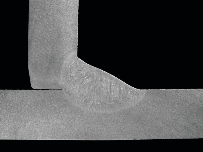
POSSIBLE CAUSES | HOW TO AVOID? |
|---|---|
Incorrect torch/electrode angle | Use the correct torch/electrode angles |
Too large a weld pool | Reduce the deposition rate |
Magnetic arc blow | Move the earth return clamp, use the shortest arc possible, reduce the welding current, angle the torch/electrode opposite the direction of arc blow, and/or use an AC power source |
Excess weld metal (weld reinforcement)
Excess weld metal, also known as weld reinforcement, occurs when the volume of weld metal deposited in the joint exceeds what is necessary for the intended strength and contour of the weld. While some reinforcement is typically required to compensate for weld shrinkage and ensure the weld is strong enough, excessive weld metal goes beyond this, leading to a build-up that can affect the aesthetic and functional aspects of the weld. This surplus can lead to increased stress concentrations, unnecessary weight, and material wastage, as well as potential difficulties in meeting dimensional tolerances and can affect the performance in service by altering the stress distribution within the welded component. Managing the amount of weld metal is crucial for achieving an efficient, cost-effective, and structurally sound weld that meets the specified design and quality standards.
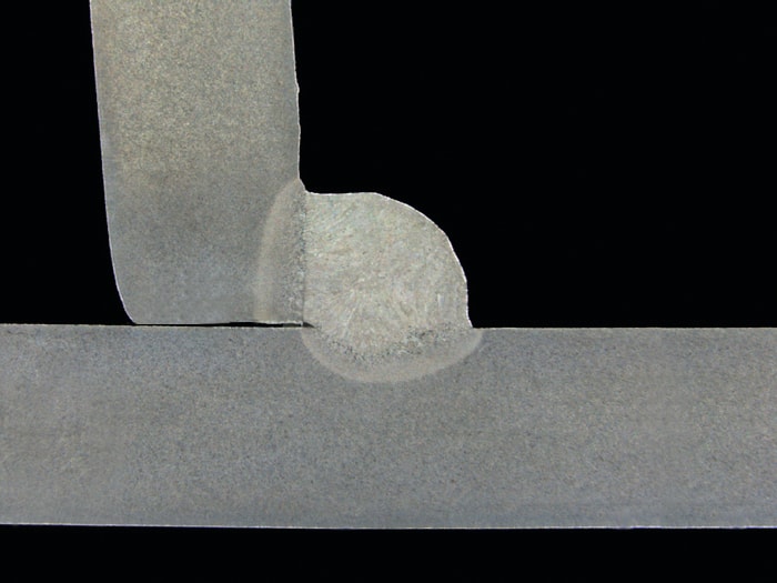
POSSIBLE CAUSES | HOW TO AVOID? |
|---|---|
Too much filler metal for the welding speed used | Increase the welding speed or reduce the amount of filler metal |
Too large an electrode diameter | Use a smaller diameter electrode, or increase the joint angle |
Too small or unbeveled groove | Use beveled groove |
Too low heat input | Use higher heat input |
Cracks (e.g. hot cracking)
Cracks in welding, such as hot cracking, are one of the most severe defects that can occur during the welding process. These cracks occur when localized stresses exceed the ultimate tensile strength of the base metal. Stresses develop as the weld cools and solidifies. This type of cracking can be caused by many factors, including improper filler material selection, high levels of impurities in the base metal, excessive heat input, and rapid cooling rates. It is essential to understand the mechanisms behind hot cracking and follow proper welding practices to prevent this detrimental defect, which ensures the integrity and longevity of welded structures.
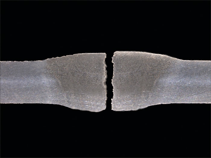
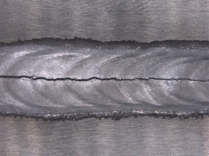
POSSIBLE CAUSES | HOW TO AVOID? |
|---|---|
Too low a width-to-depth ratio for the weld | Ensure that the width-to-depth ratio of the weld is above 1 with non-alloy steels / above 1.5 with stainless steels |
High stresses due to the large amount of thermal expansion | Minimize the degree of restraint by using appropriate edge preparation and accurate joint fit-up |
High carbon content in the weld | Use a low carbon content filler material |
Wrong filler metal | Use right filler metal |
Segregation of impurities to the center of the weld | Choose a base material with less impurities |

Susanna Norja
Susanna Norja
Editor-in-chief of the Welding Value blog, content producer and Social Media Manager at Kemppi until March 2024.
