Calculation of heat input in MIG/MAG welding

L'ABC du soudage

Calculation of heat input in MIG/MAG welding

28 juillet 2020

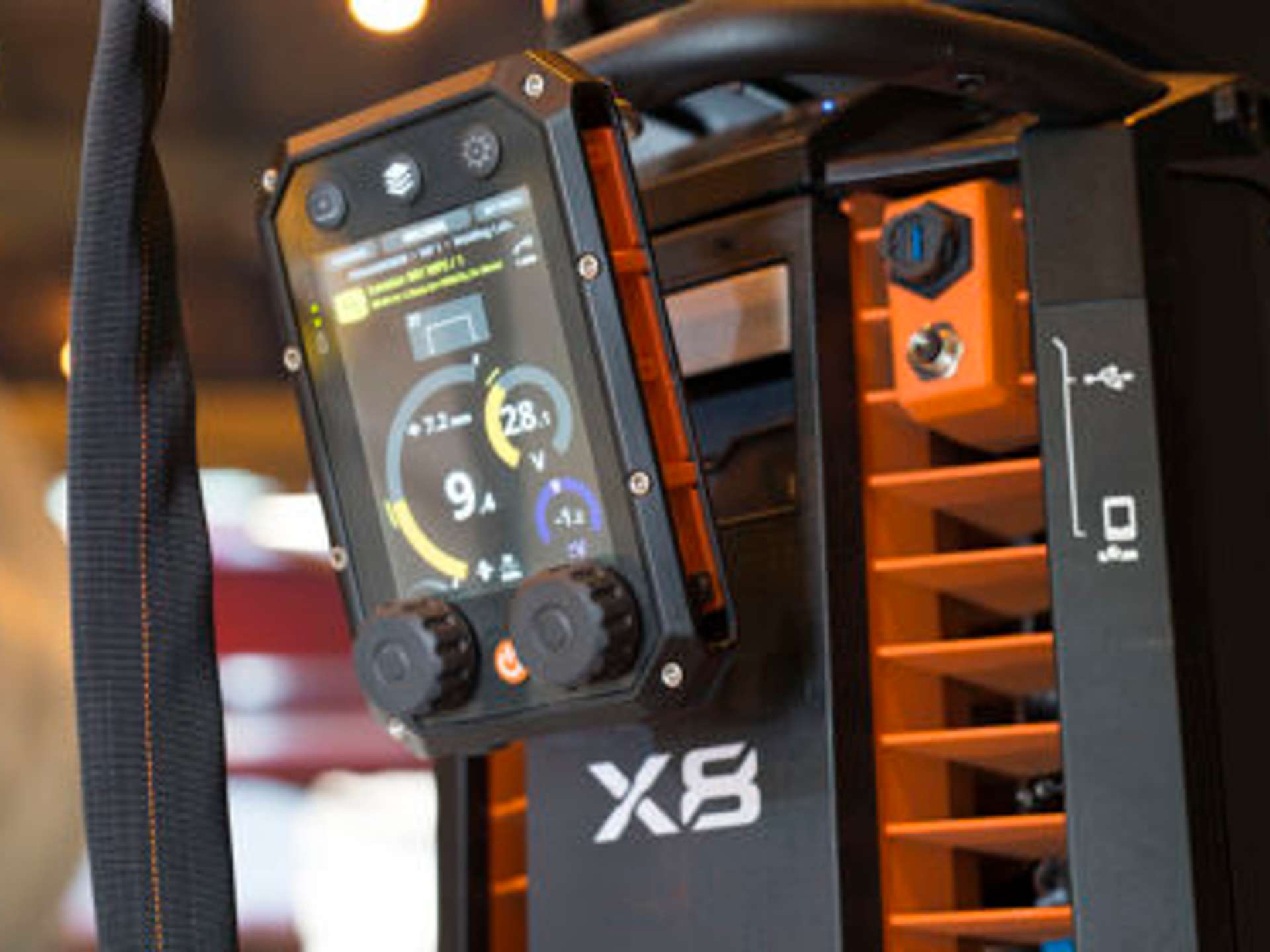
The new welding procedure test standard, EN-ISO 15614-1:2017, provides recommendations for the measurement and calculation of heat input. In concrete terms, what does this mean for MIG/MAG welding? And how can workshops carry out these calculations in practice?

Jani Kumpulainen

Understanding the new welding procedure test standard

Section 8.4.7 of the EN-ISO 15614-1:2017 standard, titled “Heat input (arc energy)", states the following for the new welding test procedure:

"Users can use either heat input or arc energy (J/mm). Arc energy must be calculated in accordance with ISO/TR 18491. The k factor pursuant to ISO/TR 17671‑1 must be taken into account in the calculation of heat input. The calculation (of either heat input or arc energy) must be documented."

"Arc energy and heat input both indicate the heat that arises as a result of the welding arc. In the past, these were regarded as alternative terms for the same quantity, but they are now calculated via different formulae. Users can use heat input or arc energy in the monitoring of welds, to be calculated in accordance with ISO/TR 18491."

The new welding procedure test standard refers to the technical reports for ISO/TR 18491 and 17671-1, which state that arc voltage must be measured as close to the arc as possible. This way, voltage losses caused by welding cables can be eliminated. Table 1 presents the recommended measurement points for various welding processes.

Table 1. Voltage measurement points for various welding processes in accordance with the ISO/TR 18491 guidelines

Formulae for calculating arc energy

Pursuant to the ISO/TR 18491 report, formulae A, B, and C are used to calculate arc energy. The terms applied are presented in Table 2.

Table 2. Terms used for calculating arc energy in accordance with the ISO/TR 18491 guidelines

How are the formulae applied?

Formulae A, B, and C are suitable for non-waveform-controlled welding methods. Only formulae B and C may be used for calculations related to waveform-controlled welding methods. Instantaneous energy or power must be measured with an external meter if the welding machine does not display it. In both cases, the sampling frequency must be no less than 10 times the waveform frequency.

ISO/TR 18491 defines waveform-controlled welding thus:

“Welding process modification of the voltage and/or current wave shape to control characteristics such as droplet shape, penetration, wetting, bead shape, or transfer mode(s).”

The heat input calculation formula

The ISO/TR 17671-1 standard presents the thermal efficiencies of various welding processes and a formula for calculating heat input:

Table 3. Welding processes’ thermal efficiencies according to ISO/TR 17671-1

To determine heat input, we must first calculate the arc energy and multiply it by the thermal efficiency. Below, we provide an example of the calculation of arc energy (E) and heat input (Q) in MIG/MAG welding. Such calculations that use averages for the current and the voltage are applicable only for non-waveform-controlled welding:

High welding currents and thin welding cables lead to voltage losses

Arc voltage must be measured as close to the arc as possible, to eliminate voltage losses caused by welding cables. In practice, what are the factors that influence voltage losses?

Table 4. Voltage losses in ground and intermediate cables over 10 meters

Table 5. Voltage losses in a 4.5-meter MIG/MAG welding torch

Example:

  • 30-meter, 70 mm2 interconnection cable

  • 30-meter, 70 mm2 ground cable

  • 420 A, 4.5-meter liquid-cooled welding torch

The welding parameters from the power source are 500 A and 39 V (19.5 kW). Voltage loss is 9.55 V, and power loss is 4.8 kW. This shows that the voltage losses are at their greatest when long and thin welding cables and high welding currents are used.

Performing practical welding tests to measure the effective and calculated power

Let’s revisit the heat input calculation method presented in ISO/TR 18491. Method A, which uses averages for the welding current (I) and the arc voltage (U), is suitable for non-waveform-controlled welding. In contrast, methods B and C measure instantaneous energy (IE) or power (IP), which is required for the calculations for waveform-controlled welding. These methods can be used also for non-waveform-controlled welding processes.

The definition of waveform-controlled welding is not clear-cut, and that may give rise to differing interpretations. Because of this, we carried out practical welding tests to measure the effective and calculated power (averages were used for the current and the voltage in these calculations).

The welding tests were performed with Kemppi’s X8 MIG Welder welding machine, ER70S-6 Ø 1.2 mm solid wire, and Ar + 18% CO2 mixed gas. Welding was carried out in the form of standard and pulsed-MAG welding in various power ranges.

Table 6 presents the results from the MAG welding tests, which show an error value of 12.8% at the lowest measured value (59 A). As the power is increased, the error decreases, and it is no longer significant at currents exceeding 200 A.

Table 6. Results of MAG welding tests

Table 7 presents results from pulsed MAG welding tests which demonstrate that error is present across the entire power range. The relative error is at its greatest at low power.

Table 7. Results of pulsed MAG welding tests

Visual comparison between MAG and pulsed MAG welding test results

How new MIG/MAG machines make heat input calculations easier

Calculating heat input does not have to be difficult; Kemppi’s latest MIG/MAG welding machine makes such calculations easier. The X8 MIG Welder measures arc voltage directly at the contact tip, to eliminate voltage losses. It calculates instantaneous power as per the standards and has a sampling frequency of up to 20,000 Hz. The device can also determine the welding speed when the welder indicates the weld length upon completion of the weld. After this, the machine automatically displays the effective heat input.

This feature makes jobs such as filling in Welding Procedure Qualification Records easier since the required information on welding parameters, welding speed, and heat input is automatically generated by the X8 Control Pad unit after welding.

After welding, the welder sees the actual welding parameters, welding speed, and heat input from the X8 Control Pad’s display.

So what is the take-home message here? From the perspective of heat input calculations, voltage measurements should be carried out as close to the arc as possible because of voltage losses caused by welding cables. At least in pulsed-MAG welding, the effective power should be used in the calculations, because some level of error occurs across the whole power range.

However, performing calculations with pen and paper is a thing of the past, because the latest MIG/MAG machines make life a little bit easier for welding engineers, offering accurate automated calculation of heat input.

Jani Kumpulainen
Author

Jani Kumpulainen

Welding Technology Manager at Kemppi Oy. International Welding Engineer (IWE) and Inspector (IWI-C) who has over 10 years of experience as a welding expert in welding process development, welding coordination of pressure vessels and international sales. Interested in understanding the whole welding industry including welding processes, weldable materials, and welding quality standards.

Inscrivez-vous à notre newsletter et soyez parmi les premiers à découvrir les dernières actualités de Kemppi.

En vous abonnant, vous acceptez de recevoir des e-mails marketing de Kemppi.

Le précurseur du soudage à l'arc

Kemppi s’impose comme le leader en matière de conception dans l’industrie du soudage à l'arc. Grâce à l'optimisation continue de l'arc de soudage, nous nous engageons à améliorer la qualité et la productivité du soudage, tout en œuvrant pour un monde plus respectueux de l'environnement et plus équitable. Kemppi propose des produits durables, des solutions numériques et des services destinés aux professionnels, qu'il s'agisse de grandes entreprises industrielles ou d’entrepreneurs. La fiabilité et la simplicité d'utilisation de nos produits sont au cœur de notre philosophie. Fort d’un réseau de partenaires hautement qualifiés dans plus de 70 pays, nous rendons notre expertise accessible à l'échelle mondiale. Basée à Lahti, en Finlande, Kemppi compte plus de 650 professionnels dans 16 pays et a réalisé un chiffre d'affaires de 209 millions d'euros en 2023.

Kemppi – Designed for welders

Copyright © 2024 Kemppi Oy